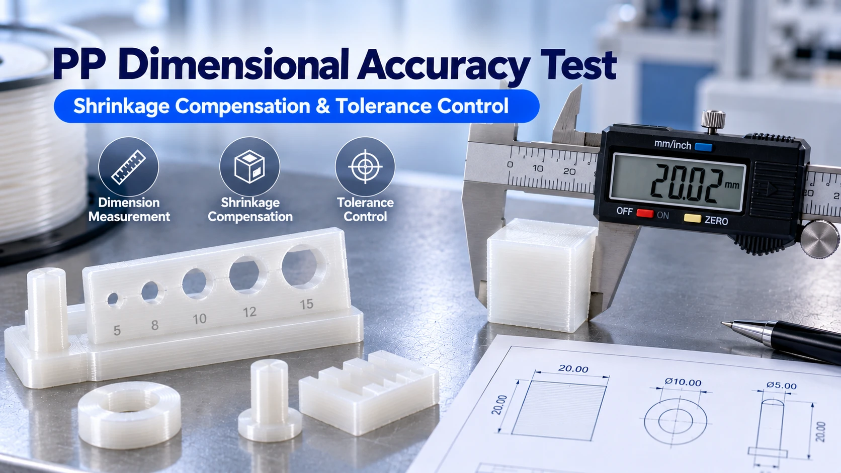
Are PP Prints Dimensionally Accurate? Shrinkage Compensation and Tolerance Control
Are PP prints dimensionally accurate?
PP printed parts can achieve a practical level of dimensional accuracy, but only if you understand their shrinkage behavior and apply calibration compensation.
PP is a semi-crystalline material; printed parts shrink as they cool, and the crystallization process also causes volumetric changes. Therefore, if you simply copy the printing parameters used for PLA, PETG or other materials, PP parts may end up undersized, with changed hole diameters or local warping.
Throughshrinkage compensation, structural design and iterative testing, you can better control the dimensions of PP printed parts.
For modified PP 3D printing materials, such as POLIVE PPpro™, the material formulation can be optimized for shrinkage and deformation during 3D printing. However, the specific compensation ratio should still be based on the actual material, printer and test data, rather than using a fixed value that applies to all printing conditions.
Where does PP shrinkage come from?
The dimensional changes of PP printed parts can mainly be understood from two aspects:
- Thermal shrinkage as the melt cools from high temperature to room temperature
- Volumetric changes during crystallization of the semi-crystalline material
The actual shrinkage is affected by factors such as material formulation, crystallization behavior, cooling rate and printed structure.
More importantly, PP shrinkage is not necessarily uniform.
For example, when a part has significant wall-thickness differences at different locations, the thicker and thinner regions cool at different rates, which can produce different degrees of shrinkage, leading to:
- Edge curling
- local deformation
- Bulging
- Flat-surface bending
- Round holes becoming oval
Therefore, controlling PP dimensional accuracy is not just a matter of simply setting a “shrinkage rate.”
How should shrinkage compensation be set?
Most slicer software provides compensation functions related to model dimensions, such as XY dimensional compensation or Horizontal expansion.
The basic idea is:
, which slightly adjust the model size before printing to offset the dimensional changes produced during printing.
However, it is not recommended to simply copy other usersâ compensation values.
A more reliable approach is to first print a calibration part with known dimensions, for example:
- Standard cube
- Round hole
- Cylinder or pin
- Hole arrays of different sizes
- Critical mating features in the actual product
After printing, measure the sample once it has cooled and stabilized to room temperature.
For example, if the designed model dimension is 20.00 mm but the actual printed measurement is 19.70 mm, you can further adjust the compensation parameters based on the actual deviation, then print the next round for verification.
In this way, you can gradually build up compensation values suited toa specific material + a specific printer + specific parameters.
Why do hole diameters need separate calibration?
Hole features are often more complex than external dimensions.
A round hole designed at 10 mm may end up noticeably smaller than 10 mm after printing.
This is because the hole diameter is affected not only by material shrinkage, but also by:
- Extrusion width
- nozzle diameter
- Print path
- Arc resolution
- Material flow
- Local shrinkage
and other factors.
Therefore,External dimensions and internal hole diameters cannot simply use the same compensation logic.
If the part requires pin-hole fits, shaft-hole fits or threaded structures, it is recommended to print separate test pieces for these critical dimensions rather than calibrating only a standard cube.
Which process variables affect PP tolerances?
1. Wall thickness
The more pronounced the wall-thickness variation, the more likely different regions will show differences in cooling and shrinkage behavior.
Therefore, for parts requiring high dimensional consistency, try to avoid very abrupt wall-thickness changes.
Where the structure allows, you can use:
- Uniform wall thickness
- Adding fillets
- Optimizing transition structures
to reduce local stress and deformation.
2. Infill density
The infill structure also affects the internal heat distribution and shrinkage behavior of the part.
Generally, the higher the infill density, the more internal material there is, and the heat and residual stress generated during printing may also increase.
Therefore, for parts with high dimensional accuracy requirements, you should not focus only on the outer contour but also consider the internal infill structure.
3. Cooling stability
Cooling conditions are very important for the dimensional stability of PP printed parts.
If the cooling rates of different regions of the part differ significantly, uneven shrinkage may occur.
For example:
- One side directly exposed to airflow
- Different regions of the part have different heat dissipation conditions
- Large ambient temperature fluctuations
- The chamber temperature changes significantly during printing
can all affect the final dimensions.
Therefore, rather than simply pursuing stronger cooling, sometimes it is more important to keep the entire printing processstable and repeatable thermal environment.
Printing orientation also affects dimensions
The dimensions of PP printed parts are not exactly the same in all directions.
Generally, dimensional control within the XY plane is directly related to the print path, while Z-direction dimensions are also affected by the layer height, inter-layer stacking and thermal shrinkage during printing.
Therefore, for parts requiring precise fits, you need to consider based on the actual function:
- Which direction is the critical dimension
- Which direction bears the main load
- Which dimensions need post-processing
- Which dimensions need reserved adjustment margin
If a part contains multiple high-precision mating surfaces at the same time, it is best to calibrate against the actual structure rather than assuming all directions can use the same dimensional compensation value.
Why are the heated bed and printing environment also important?
PP dimensional stability depends not only on the nozzle temperature.
The bed temperature, ambient temperature and the stability of the overall temperature during printing can all affect the cooling and shrinkage of the part.
If the printing environment changes significantly, even with the same slicing parameters, parts from different batches may show dimensional differences.
Therefore, for PP printed parts requiring mass production, it is recommended to keep the following as fixed as possible:
- The same printer
- The same material batch
- The same nozzle
- The same printing parameters
- Similar environmental conditions
This makes it easier to establish a stable, repeatable dimensional control process.
How to calibrate PP printing dimensions?
A practical calibration process can be divided into four steps.
Step 1: Print a calibration part
Choose a test model with clearly defined dimensions, for example:
- 20 Ã 20 Ã 20 mm cube
- Round holes of different sizes
- Pin
- Critical mating features in the actual product
Do not measure immediately after printing.
Step 2: Measure after cooling
A freshly printed part may still contain residual heat and stress internally.
Therefore, you should wait until the sample has cooled and stabilized to room temperature before measuring.
Record:
Design dimension â Actual dimension â Dimensional deviation
For example:
Design dimension: 20.00 mm
Actual dimension: 19.70 mm
Deviation: -0.30 mm
With multiple sets of dimensions, you can better judge whether the dimensional deviation is regular.
Step 3: Adjust shrinkage compensation
Adjust the XY dimensional compensation or other relevant parameters based on the measurement results.
Then reprint the same calibration part.
The purpose of the second-round test is not to achieve perfection in one shot, but to verify whether the first adjustment is effective.
Through multiple rounds of testing, you can gradually find parameters suited to the current material and printing conditions.
Step 4: Test the actual fit
A standard calibration cube only indicates basic dimensional changes.
When it comes to actual function, you should also test the real fit, for example:
- Pin and hole
- Shaft and shaft hole
- Snaps
- Threads
- Plug-in structures
- Sliding structures
Because actual fit, besides dimensional error, is also affected bysurface friction, print texture and material elastic deformation.
Therefore, for functional parts,“dimensionally accurate” does not necessarily mean “fits properly.”
Do not pursue absolute dimensional accuracy alone
For actual product design, rather than pursuing a theoretical “absolute accuracy,” it is more important to determine aacceptable tolerance range.
that can be stably repeated. For example, a hole that needs to insert into another part does not necessarily require a certain absolute dimension, but rather needs to:
- Be able to insert smoothly
- Not be too loose
- Not jam
- Retain function after long-term use
Therefore, you can design a certain adjustment margin based on the actual application.
For some structures, you can also adopt:
- Slot holes
- Adjustable mounting holes
- Fitting allowance
- Replaceable mating parts
- Split structures
These designs are usually more pragmatic than simply pursuing “absolutely precise” dimensions from the printer.
How should PPpro⢠shrinkage compensation be set?
For POLIVE PPpro™, the specific shrinkage compensation parameters should be based on actual test data.
Different printers, nozzles, temperatures, print speeds, model sizes and thermal environments can all affect the final result; therefore, it is not recommended to treat a certain fixed compensation ratio as applicable to all equipment and parts.
If you need to establish your own PPpro⢠dimensional compensation parameters, you can follow:
Material â Printer â Parameters â Calibration part â Measurement â Compensation â Verification
to build your own parameter library following this process.
PPproâ¢âs specific shrinkage test data and recommended compensation values can be further supplemented based on actual test results.
Summary
The dimensional accuracy of PP printed parts can reach a practical level, but it needs to be calibrated for PPâs shrinkage characteristics.
Key points to note:
- PP shrinkage comes from thermal shrinkage and the crystallization process.
- Uneven shrinkage can cause warping and dimensional deviations.
- Shrinkage compensation is best derived from measurements of calibration parts.
- Hole diameters usually require separate dimensional calibration.
- Wall thickness, infill, cooling and printing orientation all affect dimensional stability.
- For batch printing, try to fix the equipment, material and process conditions as much as possible.
- Critical mating parts should be tested for actual fit, not just measured for a single dimension.
- For functional parts, reasonably designed tolerances and adjustment margins are often more important than pursuing absolute accuracy.
If you need to further control the dimensions of PP printed parts, you can establish suitable POLIVE PPpro™ shrinkage compensation parameters through actual calibration data, thereby gradually turning dimensional control from “empirical adjustment” into a repeatable process.
How Accurate Are the Dimensions of PP Prints?
Practical accuracy is achievable, but only if you first understand its shrinkage behaviour and calibrate compensation. PLA experience cannot be carried over directly.
Why Do Hole Diameters Need Separate Calibration?
Holes are affected by the extrusion path, shrinkage and first-layer squish, so their deviation pattern differs from outer dimensions. Print a calibration part, measure it after cooling, then set outer-dimension and hole-diameter compensation separately.
Which Process Variables Change the Tolerance?
Wall thickness, infill density, cooling stability, print orientation, plus build plate condition and ambient temperature. We recommend open heat dissipation in an air-conditioned room away from draughts: making shrinkage predictable helps more than endlessly tweaking compensation values.
Should You Chase Absolute Dimensional Accuracy?
No. For functional parts, prioritise assembly clearance and fit feel, use rounded corners and uniform wall thickness to reduce distortion, then calibrate against real measurements. That is far more useful than chasing two decimal places.
Related Reading
- 为什么 PP 以前这么难打?收缩、翘边、粘不住的三大难题
- How to Design PP Parts for 3D Printing? Wall Thickness, Fillets, Snap Fits and Warp Prevention
- How to Configure PP 3D Printing Settings? PPpro™ Parameter Guide