How to Design PP Parts for 3D Printing? Wall Thickness, Fillets, Snap Fits and Warp Prevention
Design out warping first: fillet sharp corners, add mouse ears, widen the bottom contact area and keep wall thickness uniform across the part.
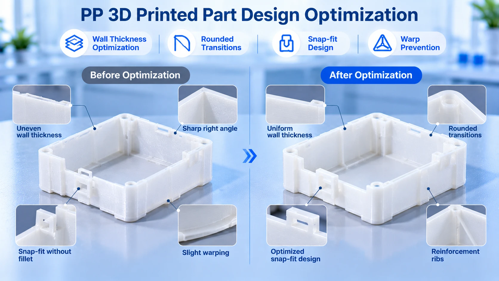
Designing PP parts for FDM printing requires considering both material properties and the printing process. Keeping wall thickness as uniform as possible, smoothing corner transitions, leaving reasonable deformation space for snap fits, and combining that with proper part orientation and structural reinforcement can substantially improve printability and assembly performance.
PP is a semi-crystalline material, and its cooling and crystallization processes affect dimensional change. For structures at risk of shrinkage and warping, beyond choosing the right material, you must reduce unnecessary stress concentration and uneven shrinkage starting at the design stage.
Wall Thickness: Uniformity Matters More Than Simply Thickening
In wall-thickness design, uniformity comes first. Sudden changes in wall thickness can cause different cooling and shrinkage between regions, raising the risk of warping, local deformation, or internal stress concentration.
You can follow these guidelines when designing:
Keep wall thickness uniform first: avoid sudden local thickening or thinning wherever possible.
Reinforce locally based on load locations: add material where neededâscrew holes, joints, and load-bearing areasârather than thickening the entire part.
Use hollow structures sensibly: for shells and enclosures, a hollow structure with ribs usually saves more material than large solid fills.
Set wall thickness in line with printing conditions: wall thickness must match nozzle size, number of outline perimeters, part size, and actual load requirements.
For FDM prints, increasing the number of outer perimeters often helps wall strength, but you cannot simply assume that more perimeters and higher infill make a part more reliable. Structural design, interlayer bonding, and print orientation matter just as much.
The specific wall thickness must be determined by trial prints and functional testingâdo not treat any fixed value as a universal standard for all PP parts.
Fillets and Transitions: Reduce Stress Concentration
Right-angle inner corners easily create stress concentration. Under tension, bending, or impact, these locations can become the starting points of cracks or local failure.
Adding appropriate fillets makes the geometry transition more gradually, improving local load-bearing behavior.
When designing, focus your checks on these locations:
Inner corners: add fillets where space allows to reduce sharp transitions.
Wall-thickness junctions: connect regions of different thickness with gradual transitions; avoid sudden thick blocks.
Near holes and openings: check whether there are overly narrow material zones between the hole edge and surrounding structure.
Snap-fit roots: use suitable fillets to lower stress concentration during bending.
Exposed edges: add chamfers per assembly and usage needs to improve edge finishing and assembly experience.
Fillet size must be set based on part space, wall thickness, and load direction. For repeatedly bent structures, fillets alone cannot solve everythingâthickness, bending length, and print layer direction must also be considered.
Snap Fits and Living Hinges: Leave Room for Elastic Deformation
PP has a degree of toughness and repeated-bending potential, making it suitable for snap fits, flexible connections, and one-piece living hinges. But toughness does not mean every snap fit will last longâgeometry, print orientation, and actual usage conditions all affect service life.
Key details of snap-fit design
Cantilever length and thickness
Cantilever snap fits rely on elastic deformation for assembly and release. Cantilever length, thickness, and deflection distance together determine the required assembly force and root stress.
A snap fit that is too short or too thick may require excessive assembly force; one that is too long or too thin may lack sufficient retention. Design must balance the target deflection and available space.
Insertion and release angles
The insertion face and the retaining face can be designed with different geometries. The insertion face should allow smooth assembly, while the retaining face must provide enough locking. The exact angles depend on the snap-fit structure, material elasticity, and disassembly needs.
Root fillet
The snap-fit root is a key inspection area. Adding proper fillets and avoiding sudden wall-thickness changes help reduce local stress concentration.
Cycle testing
Snap-fit reliability cannot be judged by the first engagement alone. It is recommended to repeatedly perform assembly and disassembly tests on actual printed parts, checking for cracks, permanent deformation, reduced retention, or root damage.
What to watch for in living-hinge design?
A living hinge connects two relatively rigid sections via a thin flexible region. PP is commonly used for such structures, but FDM-printed living hinges are also affected by interlayer bonding and local geometry.
During design, focus on:
Thickness and width of the hinge region.
Transition shape where the hinge meets the main body.
Relationship between the actual bending direction and the print layer direction.
Whether there is excessive stretching or local folding during opening/closing.
Cracks, deformation, and functional changes after repeated opening/closing.
For hinges that will be used repeatedly, run cycle tests on real printed parts rather than judging durability from the material name or a single bend.
Preventing Deformation: From Structural Design to Part Placement
Controlling deformation in PP parts requires coordination between design and the printing process. Even with a sound structure, an unsuitable orientation or uneven cooling will still affect final dimensions.
1. Reduce large, continuous flat surfaces
Large flat plates and wide enclosure bases are more prone to uneven shrinkage. You can add shallow ribs, grooves, curved surfaces, or other geometric features as needed to change local stiffness and reduce unnecessary large flat areas.
These structures do not guarantee complete elimination of warping; their effect must still be verified by actual printing.
2. Arrange ribs sensibly
Ribs improve the stiffness of thin-wall structures and reduce in-use bending. But ribs that are too thick, or sudden thickening at junctions, can also introduce new shrinkage differences.
Design ribs to connect smoothly with the main body and position them along the part’s load direction. The number and size of ribs should be based on actual functional needsâmore is not always better.
3. Choose a suitable print orientation
Print orientation affects interlayer bonding, dimensional performance, and support needs.
When orienting the part, consider comprehensively:
Which dimensions are most sensitive to accuracy.
Which direction the main load acts on.
The bending direction of snap fits and hinges.
Which surfaces must keep a good appearance.
Whether there are edges prone to lifting or large contact areas.
For elongated parts, you can measure how different orientations affect dimensions and warping. For functional structures like snap fits, also evaluate how orientation affects interlayer bonding and bending life.
4. Maintain cooling uniformity
Cooling conditions during printing affect the shrinkage and dimensional stability of PP parts. Rather than fixating on a single parameter, prioritize keeping the entire part’s cooling process as uniform as possible.
With POLIVE PPproâ¢, you can use a print style that needs no heated bed, prints at room temperature, and runs with the door and lid open; an air-conditioned room generally helps keep the environment stable. Actual results still depend on part geometry, printing conditions, and the surrounding environment.
How to verify whether a PP part design is sound?
After design, verify the key structures against the actual usage scenario, rather than only checking whether the part printed successfully.
| Verification item | Key observations |
| Dimensional check | Key dimensions, hole positions, assembly clearance, and batch-to-batch variation |
| Flatness and warping | Whether the base is flat and edges lift |
| Snap-fit test | Assembly force, retention, permanent deformation, and cracks |
| Living-hinge test | Opening/closing behavior, damage at the bend region, and changes after cycling |
| Structural strength | Whether bending, cracking, or failure occurs under actual load |
| Environmental adaptability | Evaluate temperature, chemical contact, or other service conditions based on the application |
When problems arise in testing, analyze the cause based on the failure location. For example, cracking at a snap-fit root may relate to geometry, interlayer bonding, or deflection; base warping requires checking part structure, orientation, and cooling conditions together.
Adjust only a few key factors at a time when iterating, so it is easier to tell whether a change truly improved part performance.
Summary
Designing PP 3D-printed parts is not mainly about simply adding wall thickness or reinforcement, but about making geometry, material properties, and printing process work together.
Wall thicknessWall thickness: keep it uniform first, and reinforce locally based on load needs.
Fillets: reduce sharp corners and abrupt thickness changes to lower the risk of stress concentration.
Snap fits and living hinges: design deformation space sensibly, and verify reliability through repeated cycle tests.
Deformation control: control dimensional change by combining structural features, print orientation, and uniform cooling.
Practical verification: confirm the design outcome through dimensional measurement, assembly testing, and functional testing.
Modified PP filaments like POLIVE PPpro⢠combine these structural-design principles with real printing conditions, helping improve part printability and more specifically addressing warping, assembly, and functional issues.
Related Reading
·Can PP Make Living Hinges? Printing One-Piece Living Hinges with POLIVE PPpro™
·How to Configure PP 3D Printing Settings? PPpro™ Parameter Guide
·Can 3D Printing Make Packaging Prototypes? Clamshell Boxes, Snap Fits and One-Piece Molding
How Should Wall Thickness Be Set for PP Parts?
Uniformity matters more than simply adding thickness. Abrupt changes in wall thickness cause uneven cooling and stress concentration, and are a common source of warping and cracking; when reinforcement is needed, prefer gradual transitions and rounded fillets.
Why Are Rounded Corners So Important?
Right angles are stress concentrators and are the first places to lift as the part cools and shrinks. Rounding the outer profile and the bottom corners reduces the risk of warping while also improving drop resistance.
How Should the Base Be Designed to Prevent Warping?
Enlarge the bottom contact area, add thickened mouse ears at the corners and use a brim where needed. That structural approach is exactly what we rely on for large-base parts, combined with PPLOCK26811 — no heated bed and no enclosure.
What Clearance Should Be Allowed for Snap-Fits and Living Hinges?
Leave room for elastic deformation and a bend radius, and avoid sharp corners at the root. Validate against the actual number of opening and closing cycles rather than judging from a single assembly by feel.
How Do You Verify That a Design Is Sound?
Print a combined test part with a large flat base, thin walls, rounded transitions and a snap-fit, then check for warping after cooling, measure the assembly dimensions and cycle the joint repeatedly. If something is off, fix the geometry before touching print settings.